
Здравствуйте, гость ( Вход | Регистрация )

  |

 7.1.2016, 23:08 7.1.2016, 23:08
Сообщение
#1061
|
|
 Прописался  Группа: Пользователи Сообщений: 121 Регистрация: 7.4.2014 Пользователь №: 70 606 Реальное имя: Буч 
|
Цитата(Иваноff @ 6.1.2016, 16:00)  После выключения зажигания все перестало работать, а именно сигналка не закрывает, дежурный свет не загорается, аварийка не работает, центральный замок тоже, звуковое оповещение и т.д. Ключик на себя, и, о Боги! Все оживает... дык может банально мантит замок: либо из-за задроченности сувальд, либо ключа, либо и того и другого, что скорее всего... Со вторым ключем тоже самое? |
 |
 
|


|
7.1.2016, 23:29
Сообщение
#1062
|
|
|
Прописался Группа: Пользователи Сообщений: 121 Регистрация: 7.4.2014 Пользователь №: 70 606 Реальное имя: Буч
|
Цитата(Avtandil @ 4.1.2016, 14:12) остановился на пункте оплаты проезда, машину не глушил, свет не выключал... что значит "свет не выключал"? Какой? Дверь при этом открывал только водительскую?Цитата(Avtandil @ 4.1.2016, 14:12) По возвращении в машину обратил внимание, что не погас свет в салоне. На действия "крутилки" на приборной панели реакции ноль. Впереди и в середине отключил свет кнопками, на пятой двери остался гореть... какие двери открывал/закрывал "по возвращении"?Цитата(Avtandil @ 4.1.2016, 14:12) отметка о выполненном реколе G07 и перечень работ - "...тест приборной панели. Доработка проводки. Перепрограммирование модуля CCN..." Вот и возник вопрос - судя по неисправности это G07, судя по документам он устранен. судя по неисправности вообще не факт. Что касается реколла, Крайслер считает что устранен:https://www.moparownerconnect.com/oc/us/en-...4HB58N54F167731 Ты пробовал закрыть ведро не пультом, а ключем, механически?... |
|
|
|
|
8.1.2016, 12:14
Сообщение
#1063
|
|
 Прописался Группа: Пользователи Сообщений: 179 Регистрация: 9.1.2010 Из: Смоленск Пользователь №: 27 456 Реальное имя:Андрей
|
Дверь открывал только водительскую, свет не выключал головной.
"По возвращении" открывал-закрывал тоже только водительскую. Судя по ссылке висит еще рекол и на подушку??? Попробовал закрыть ключом - ЦЗ не срабатывает, закрывает только водительскую дверь. Только не совсем врубаюсь в схемотехнику - ведь свет не реагирует на "крутилку" центрального переключателя света... Сообщение отредактировал Старик Ромуальдыч - 8.1.2016, 12:15 --------------------  Dodge Durango 4.7 2004г. VIN 1D4HB58N54F167731 |
|
|
|

|
8.1.2016, 16:51
Сообщение
#1064
|
|
 Прописался Группа: Пользователи Сообщений: 113 Регистрация: 1.6.2014 Из: Пенза Пользователь №: 71 888 Реальное имя:Сергей
|
Цитата(Мутный Буч @ 8.1.2016, 1:08) ... Со вторым ключем тоже самое? Короче, Кулибин в обход того (кто его знает чего), что не работает как-то через сигналку это все реализовал. Респект ему.Коллеги не могу найти информацию по углам развала. В мануале нет, а по форуму часа два уже лажу... Маякните, буду благодарен. -------------------- Dodge Durango Limited, 4,7 L, 2005 года рождения. VIN 1D8HB58N35F568548
|
|
|
|
|
9.1.2016, 0:18
Сообщение
#1065
|
|
|
Прописался Группа: Пользователи Сообщений: 121 Регистрация: 7.4.2014 Пользователь №: 70 606 Реальное имя: Буч
|
Цитата(Иваноff @ 8.1.2016, 16:51) Коллеги не могу найти информацию по углам развала. В мануале нет, а по форуму часа два уже лажу... в мануале все есть. Смотри SUSPENSION 2 - 1:STANDARD PROCEDURE HEIGHT MEASUREMENT The vehicle suspension height MUST be measured and adjusted before performing wheel alignment procedure. Also when front suspension components have been replaced. This measure must be performed with the vehicle supporting it’s own weight and taken on both sides of the vehicle. FRONT RIDE HEIGHT MEASUREMENT 1. Inspect tires and set to correct pressure. 2. Jounce the front of the vehicle. 3. With vehicle on level ground or hoist, make the following measurements: a. Front wheel spindle (center) to ground vertical distance. b. Center of the front face of bolt on the rear leg of Lower control arm to ground vertical distance. c. Difference between spindle and control arm bolt to ground distances should be 81mm+/-3.2mm. Note that the control arm bolt is lower than the spindle. 4. If adjustment is required, turn the torsion bar adjuster bolts- if lowering ride height, unscrew Torsion bar adjuster bolt beyond desired point so as to set height when screwing-in adjuster bolt. 5. After making any ride height adjustment, roll vehicle preferably jouncing it also, to relieve camber Effects and then re-measure Lower control arm bolt to ground height. 6. Repeat the previous steps until the ride height is within specifications. REAR RIDE HEIGHT MEASUREMENT 1. Inspect tires and set to correct pressure. 2. Jounce the front of the vehicle. 3. With vehicle on level ground or hoist, make the following measurements: a. Distance from the landing pad of the jounce bumper on the axle side to the jounce bumper cup lip of the frame side. b. The difference between the jounce bumper landing pad and the jounce bumper cup lip the reading should be 148 mm +/-10 mm for 9.259 axle, 154 mm +/-10 mm for 8.259 axle.  |
|
|
|
|
9.1.2016, 13:35
Сообщение
#1066
|
|
|
Прописался Группа: Пользователи Сообщений: 113 Регистрация: 1.6.2014 Из: Пенза Пользователь №: 71 888 Реальное имя:Сергей
|
Большое спасибо!
-------------------- Dodge Durango Limited, 4,7 L, 2005 года рождения. VIN 1D8HB58N35F568548
|
|
|
|
|
10.1.2016, 11:21
Сообщение
#1067
|
|
|
Прописался Группа: Пользователи Сообщений: 131 Регистрация: 14.10.2012 Из: Мск Пользователь №: 55 547
|
Цитата(sergey-zs @ 20.12.2015, 19:21) .... После вскрытия оказалось, что сломана заслонка холодно-горячо. Привод просто выломал ответную часть заслонки. Добрый день! А кстати, можно ли найти саму заслонку отдельно - у меня сломалась её часть, которая на шток привода заходит - поэтому заслонка "лежит" в положении "холод". Из-за этого ошибки же не должно быть? А ошибки только Старсканом считать можно? ELM, sct не видят ошибок... в продожение делов термостатных. Поменял термостат, 180F на 203F (из того, что было под рукой) - работает нормально. Корпус термостата посадил на прокладку от термостата ГАЗ-24 (2 руб. штука, FEL-PRO 35840 250 руб/шт :-) )- течи нет. Но в след раз поменяю по науке термостат с корпусом. Вопрос - если подтекает антифриз после холодного пуска с дренажного отверстия помпы - это скоро помпа помрёт? -------------------- Durango 5.7 2004 limited
1D4HB58D64F183704 |
|
|
|
|
10.1.2016, 12:33
Сообщение
#1068
|
|
 Fanatus Vulgaris Группа: Пользователи Сообщений: 11 295 Регистрация: 28.7.2007 Пользователь №: 8 687 Реальное имя: № 8 687 Город: 77
|
Цитата(2ric @ 10.1.2016, 11:21) можно ли найти саму заслонку отдельно - у меня сломалась её часть, которая на шток привода заходит - поэтому заслонка "лежит" в положении "холод".... можно, но если мне не изменяет память их там минимум 5 и гадать какая именно те нужна дело неблагодарное. Смотри номер на ней самой... Цитата(2ric @ 10.1.2016, 11:21) Из-за этого ошибки же не должно быть? если у тя шаровая в рычаге люфтит ошибки будут?...Цитата(2ric @ 10.1.2016, 11:21) А ошибки только Старсканом считать можно? ELM, sct не видят ошибок... ошибок чего?... Варианта два либо их нет, либо они не могут их считать...Цитата(2ric @ 10.1.2016, 11:21) если подтекает антифриз после холодного пуска с дренажного отверстия помпы - это скоро помпа помрёт? тепла дождись и посмотри будет течь или нет... -------------------- '03 DN SLT+ AWD
Buy The Right Part! |
|
|
|

|
10.1.2016, 12:43
Сообщение
#1069
|
|
|
Прописался Группа: Пользователи Сообщений: 131 Регистрация: 14.10.2012 Из: Мск Пользователь №: 55 547
|
я ж пишу - заслонка, которая тепло/холод потоки направляет (первая от радиаторов печки/кондишена), на схеме нет заслонок - всё в сборе. На самой заслонке тоже номера не нашёл (летом смотрел). сорри - нашёл на другой схеме 05019637АА
про ошибки - понял. ошибки по отоплению имелось ввиду. по помпе - до тепла ждать ещё два месяца... Кстати, для статистики - помпа Airtex 7168, пробег на ней 85 тыс км. Сообщение отредактировал 2ric - 10.1.2016, 12:46 -------------------- Durango 5.7 2004 limited
1D4HB58D64F183704 |
|
|
|
|
10.1.2016, 12:50
Сообщение
#1070
|
|
|
Fanatus Vulgaris Группа: Пользователи Сообщений: 6 242 Регистрация: 12.12.2007 Пользователь №: 11 047
|
напишите почту. скину схему корпуса отопителя и посмотрите заслонки
|
|
|
|
|
10.1.2016, 12:53
Сообщение
#1071
|
|
|
Прописался Группа: Пользователи Сообщений: 131 Регистрация: 14.10.2012 Из: Мск Пользователь №: 55 547
|
Цитата(ezop @ 10.1.2016, 12:50) напишите почту. скину схему корпуса отопителя и посмотрите заслонки Спасибо, нашёл уже. только, где её купить?? ссылки в сборе весь отопитель дают...
Прикрепленные файлы
-------------------- Durango 5.7 2004 limited
1D4HB58D64F183704 |
|
|
|

|
10.1.2016, 12:56
Сообщение
#1072
|
|
|
Fanatus Vulgaris Группа: Пользователи Сообщений: 6 242 Регистрация: 12.12.2007 Пользователь №: 11 047
|
это задняя печка, какой номер детали ищете?
|
|
|
|
|
10.1.2016, 12:56
Сообщение
#1073
|
|
|
Fanatus Vulgaris Группа: Пользователи Сообщений: 11 295 Регистрация: 28.7.2007 Пользователь №: 8 687 Реальное имя: № 8 687 Город: 77
|
Цитата(2ric @ 10.1.2016, 12:43) на схеме нет заслонок - всё в сборе. На самой заслонке тоже номера не нашёл (летом смотрел)... выбирай:05061400AA 05174409AA 05061403AB 05061404AA 05061407AA Цитата(2ric @ 10.1.2016, 12:43) по помпе - до тепла ждать ещё два месяца... все эти два месяца будет -20С?...
-------------------- '03 DN SLT+ AWD
Buy The Right Part! |
|
|
|
|
10.1.2016, 13:05
Сообщение
#1074
|
|
|
Прописался Группа: Пользователи Сообщений: 131 Регистрация: 14.10.2012 Из: Мск Пользователь №: 55 547
|
Diman, спасибо!
Я, наверное, в заблуждение всех ввёл - речь о задней печке... или эти номера заслонок и "взад" подойдут?? -------------------- Durango 5.7 2004 limited
1D4HB58D64F183704 |
|
|
|
|
10.1.2016, 14:19
Сообщение
#1075
|
|
|
Fanatus Vulgaris Группа: Пользователи Сообщений: 11 295 Регистрация: 28.7.2007 Пользователь №: 8 687 Реальное имя: № 8 687 Город: 77
|
Цитата(2ric @ 10.1.2016, 13:05) Я, наверное, в заблуждение всех ввёл - речь о задней печке... никто не будет хранить в своей памяти чего и где у ТЕБЯ отщекнулось. Ты не мог сразу вот эту картинку дать?...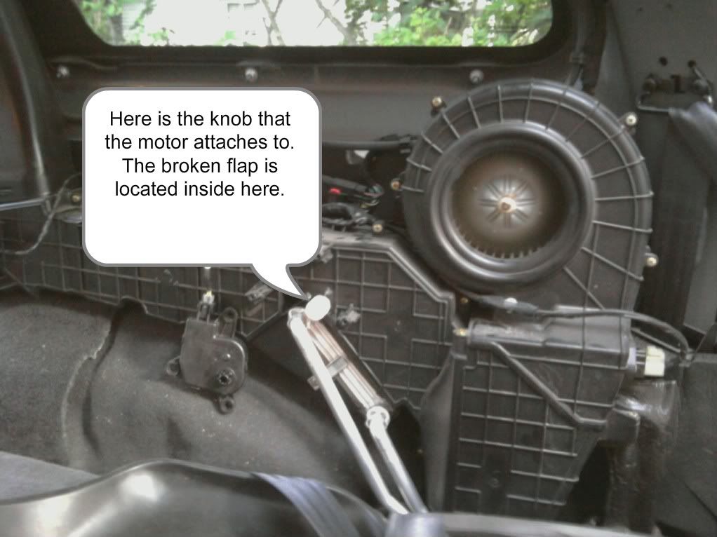 На задней печке этих заслонок две и они обе идут только в сборе с корпусом... -------------------- '03 DN SLT+ AWD
Buy The Right Part! |
|
|
|
|
11.1.2016, 15:26
Сообщение
#1076
|
|
|
Прописался Группа: Пользователи Сообщений: 179 Регистрация: 9.1.2010 Из: Смоленск Пользователь №: 27 456 Реальное имя:Андрей
|
День добрый, коллеги!
Может кто поможет мне разобраться с не выключающимся освещением салона? Напомню симптомы - свет в салоне не гаснет вообще, на действия "крутилки" на центральном переключателе света реагирует только незначительным пригасанием яркости. Из того, что смог предпринять на сегодняшний момент... 1. Прозвонил центральный переключатель света согласно мануала (все в норме). Отдельное спасибо Dimanу за помощь в доступе к мануалу! 2. Методом исключения разобрался, что при удалении предохранителя F-10 на JUNCTION BLOCKe свет в салоне не загорается, при этом не горит и подсветка кнопок блока климата. С этого преда подается постоянное напряжение на 14 и 15 pin разъема С3 приборной панели. Все остальное вроде работает (???). Но не ездить же с таким траблом?! Судя по наряд-заказам от прежнего владельца и инфы от Мутного Буча рекол G07 устранен... Куда лезть дальше? P.S. Хотя механически (ключом) открывается-закрывается только водительская дверь (это, кстати, нормально???), концевик в двери рабочий (?), т.к. при открытий двери контрольная лампочка и одометр загорается... Может рекол быть не устранен или устранен не корректно? Или я таки не там копаю? Мозг сломал уже... Ошибки при этом были вполне логичные В 1613, В 161В, В 1623 по CCN и U 0155, U 0141 по EOM. P.P.S. Пришлось вернуть назад предохранитель, на нем сидит еще и иммо... Мозг кипит...  Сообщение отредактировал Старик Ромуальдыч - 11.1.2016, 19:20 -------------------- Dodge Durango 4.7 2004г. VIN 1D4HB58N54F167731 |
|
|
|
|
11.1.2016, 21:41
Сообщение
#1077
|
|
|
Долгожитель Группа: Пользователи Сообщений: 920 Регистрация: 26.11.2009 Из: Московия-Балторуссия Пользователь №: 26 550 Реальное имя:Сергей
|
В качестве предположения, а на самом плафоне вкл/выкл не пересчелкнуто доброжелателями, случайно?
-------------------- Додж Дюранго 2004, 5,7 HEMI, чёрный, красавелла вааще!
|
|
|
|
|
11.1.2016, 21:53
Сообщение
#1078
|
|
|
Fanatus Vulgaris Группа: Пользователи Сообщений: 11 295 Регистрация: 28.7.2007 Пользователь №: 8 687 Реальное имя: № 8 687 Город: 77
|
Цитата(Avtandil @ 11.1.2016, 15:26) Судя по наряд-заказам от прежнего владельца и инфы от Мутного Буча рекол G07 устранен... тока инфы не Мутного, а инфы Крайслера. По крайней мере его дилер сообщил ему что все исправил. Может рекол быть не устранен или устранен не корректно? Насколько я помню тот реколл, там приборка должна была обнуляться, заново прошиваться, после чего проходить тест. А если она этот тест не проходила, то заменялась... Другой вопрос что: http://dodgeforum.com/forum/2nd-gen-durang...tml#post2635774 -------------------- '03 DN SLT+ AWD
Buy The Right Part! |
|
|
|
|
11.1.2016, 21:57
Сообщение
#1079
|
|
|
Fanatus Vulgaris Группа: Пользователи Сообщений: 11 295 Регистрация: 28.7.2007 Пользователь №: 8 687 Реальное имя: № 8 687 Город: 77
|
Dealer Service Instructions for:
Safety Recall G07 2004-2006 (HB) Dodge Durango Under certain operating conditions, an integrated circuit in the instrument cluster on about 326,000 of the above vehicles may overheat and result in an instrument panel fire. The instrument cluster wiring must be modified, the cluster must be tested, and the Instrument Cluster/Cabin Compartment Node (CCN) must be reprogrammed. Instrument clusters that fail the test must be replaced. NOTE: The reprogramming procedure in this recall contains a unique additional cluster self diagnostic test that must be performed. Models IMPORTANT: Some of the involved vehicles may be in dealer new vehicle inventory. Federal law requires you to complete this recall service on these vehicles before retail delivery. Dealers should also consider this requirement to apply to used vehicle inventory and should perform this recall on vehicles in for service. Involved vehicles can be determined by using the VIP inquiry process. Subject Repair Safety Recall G07 – Test and Reprogram Instrument Cluster Page 2 Dealers should attempt to minimize customer inconvenience by placing the owner in a loaner vehicle if inspection determines that instrument cluster replacement is required and the vehicle must be held overnight. Due to the small number of involved vehicles expected to require an instrument cluster, no parts will be distributed initially. Instrument clusters should be ordered only after inspection determines that repair is required. Very few vehicles are expected to require an instrument cluster. Use the following procedure to determine a “Highline” cluster from a “Lowline” cluster. �� “Highline” clusters have silver indicator needle hubs and silver rings around the gauges. �� “Lowline” clusters have white indicator needle hubs and black rings around the gauges. Model Year Part Number Description 2004 56049091AO Cluster, Instrument - Highline 2004 56049092AO Cluster, Instrument - Lowline 2005 56049691AJ Cluster, Instrument - Highline 2005 56049692AJ Cluster, Instrument - Lowline 2006 56044901AN Cluster, Instrument - Highline 2006 56044902AN Cluster, Instrument - Lowline Dealers must utilize the DealerCONNECT Exchange Order system to order a replacement instrument cluster. The order is transmitted electronically directly to the MOPAR Supplier Shipped Direct (SSD) Department. The SSD department processes orders several times a day and sends them to the DaimlerChrysler Authorized Service Centers. The Service Centers provide an exchange instrument cluster to arrive at the dealership within 24 to 48 hours of the original order. Alternate Transportation Parts Information Safety Recall G07 – Test and Reprogram Instrument Cluster Page 3 Use the following procedure to order a replacement instrument cluster: a. Open a DealerCONNECT session. b. From the DealerCONNECT home page, click on the “Parts” tab. c. Select “Exchange Order Entry” in the “Order Parts” box. d. Type in an order number and then click on “Save & Continue”. e. Fill in the information requested on the screen, then click “Save”. NOTE: Order cluster as a “Warranty Repair.” f. Click on “Submit” and then click on “OK” on the confirmation box. Refer to your Warranty Administration Manual for complete details. The original instrument cluster must be returned. Clusters ordered via DealerCONNECT Exchange Order Entry system will arrive from the Service Center with two copies of the Authorized Return Service (ARS) pre-paid UPS shipping label in the carton. Be sure to retain one copy for your records and return the other with the old instrument cluster. NOTE: The old cluster must be returned in the new cluster box. Failure to return the cluster will result in a charge to your parts account. Parts Information (Continued) Parts Return Safety Recall G07 – Test and Reprogram Instrument Cluster Page 4 The following special tools are required to perform this repair: �� CH10090 Cluster Test Harness Leads �� 6932** Connector Terminal Lock Pick �� CH9401* StarSCAN® Tool �� CH9801 StarMOBILE® Tool �� CH9804 StarMOBILE Vehicle Cable �� CH9404* StarSCAN Vehicle Cable �� CH9409* StarSCAN Documentation Kit �� CH9410* Ethernet Cable (12 ft.) �� CH9412* StarSCAN Software Update Device Kit �� Version 7.03 or higher StarSCAN Software Update CD * Part of CH9400 kit. ** Part of 8197A kit Safety Recall G07 – Test and Reprogram Instrument Cluster Page 5 A. Cluster Tests and Wiring Harness Modification 1. Use the following procedure to verify that the vehicle’s dome lights are operating properly: a. Place the instrument cluster panel dimming control in the midpoint of its travel. b. Close all the doors on the vehicle. c. Open the driver’s door and the dome light should come on. d. Close the driver’s door and the dome light should go out within approximately 45 seconds. �� If the dome operates normally continue with Step 2 of this procedure. �� If the dome light does not come on when the door is opened, troubleshoot and repair the dome light circuit as required and repeat Step 1 of this procedure. NOTE: Also check the vehicle warranty history to determine if the cluster has been replaced recently with a current level part number cluster. Replacing the cluster without modifying the wiring will result in an inoperative dome lamp. �� If the dome light remains on continuously after the door is closed, the cluster must be replaced. Record the mileage, order a new instrument cluster and store the vehicle with the battery disconnected. When the new cluster arrives, continue with Step 3, but skip Step 14 (cluster test with an ohmmeter). CAUTION: Do not return the vehicle to the customer until the new cluster is installed and wiring modifications have been performed. 2. Record the odometer reading shown on the instrument cluster. 3. Disconnect and isolate the negative battery cable. WARNING: To avoid personal injury or death, on vehicles equipped with airbags, disable the supplemental restraint system before attempting this repair. Disconnect and isolate the battery negative (ground) cable, then wait two minutes for the system capacitor to discharge before performing further diagnosis or service. This is the only sure way to disable the supplemental restraint system. Failure to take the proper precautions could result in accidental airbag deployment. Service Procedure Safety Recall G07 – Test and Reprogram Instrument Cluster Page 6 4. Remove the instrument panel knee blocker and knee blocker reinforcement. 5. Remove the brake light switch to prevent losing the adjustment setting. 6. Remove the steering column mounting nuts and lower the steering column. 7. Partially remove the center stack bezel and instrument panel end cap. 8. Remove the cluster bezel retaining screws and using a trim stick or equivalent, separate the cluster bezel from the instrument panel (Figure 1). 9. Disconnect the electrical connectors on the back of the cluster bezel and remove the instrument cluster bezel from the instrument panel. 10. Remove the four retaining screws that secure the instrument cluster to the instrument panel structural support. Safety Recall G07 – Test and Reprogram Instrument Cluster Page 7 11. Pull the instrument cluster away from the instrument panel to access and disconnect the instrument panel wire harness connectors from the instrument cluster housing (Figure 3). 12. Remove the instrument cluster from the instrument panel. CAUTION: Do not leave the instrument cluster in the face-down position for more than 20 minutes as gauge damage may occur. 13. Use the following procedure to relocate the yellow (w/orange tracer) wire in cavity number C11 of the white instrument panel cluster connector to the open cavity number C2 of the same connector: NOTE: The new cluster software will reassign the control circuit for the dome lamp to a different pin on the cluster connector. Therefore, the dome lamp wire must be relocated so that the dome lamp will function after this repair is performed. a. Lift the secondary wire lock located on the side of the white instrument cluster electrical connector (Figure 4). NOTE: The secondary wire lock only needs to be lifted approximately 1/8” to release. Safety Recall G07 – Test and Reprogram Instrument Cluster Page 8 b. Using Special Tool 6932 (part of Special Tool kit 8197A), probe the white instrument cluster electrical connector cavity from the terminal side to release the yellow (w/orange tracer) wire terminal lock (Figure 5 and 6). c. With Special tool 6932 inserted into the connector, remove the yellow (w/orange tracer) wire from the white instrument cluster connector (Figure 5 and 6). d. Install the yellow (w/orange tracer) wire into cavity C2 of the white instrument panel electrical connector (Figure 6). Pull back slightly on the wire to ensure the primary lock is engaged. e. Press the secondary wire lock down on the white instrument panel electrical connector until it is flush with the connector body. This will lock the wires into position. Safety Recall G07 – Test and Reprogram Instrument Cluster Page 9 14. If the cluster was not replaced in Step 1 test the cluster using the following procedure: NOTE: If the instrument cluster has been replaced in Step 1 of this procedure, Step 14 is not required. Continue with Step 15. a. Place the instrument cluster face down on a clean work surface. CAUTION: Make sure when the instrument cluster is laying face down on the lens that it is not being damaged or scratched and that it does not remain in this position for more than 20 minutes. b. Connect the white connector of Special Tool CH10090 to the white instrument cluster connector. NOTE: Make sure the connector is seated properly in the cluster connector. c. Connect the wires of Special Tool CH10090 to the ohmmeter terminals (Figure 7). NOTE: The polarity of the leads must be red to positive and black to common. Figure 7 Safety Recall G07 – Test and Reprogram Instrument Cluster Page 10 d. Read the ohmmeter resistance measurement: NOTE: Place ohmmeter in the “Auto” range setting if available or in the 10k range if the ohmmeter requires a manual setting. �� If the resistance reading is more than 2000 Ohms, the cluster is good. Continue with Step 15 of this procedure. NOTE: An open circuit Ohmmeter reading is considered a good cluster. �� If the resistance reading is less than 2000 Ohms, the cluster must be replaced. Follow the procedure below to replace the instrument cluster: 1. Take the VIN and odometer reading information to the parts department and order a replacement instrument cluster. CAUTION: The vehicle cannot be returned to the customer until the new cluster is installed. DO NOT reinstall the old cluster into the vehicle. 2. Temporarily install the steering column and brake switch. 3. Connect the battery and park the vehicle until the new cluster arrives 4. When the replacement cluster arrives, place the original cluster in the replacement cluster box and return the original cluster to the parts department. 5. Continue with Step 15 of this procedure. 15. Position the instrument cluster close enough to the instrument panel to connect the instrument cluster wire harness connectors to the connector receptacles on the back of the cluster (Figure 3). Position the instrument cluster into the instrument panel (Figure 2). 16. Connect the negative battery cable. 17. For vehicles that did not have the cluster replaced, reprogram (flash) the CCN module using either the StarSCAN scan tool (Section B) or the StarMOBILE scan tool (Section C) before reassembling the vehicle. For vehicles that had the cluster replaced, continue with Section D. Install Instrument Cluster NOTE: Replacement instrument clusters will already contain the latest software and do not require reprogramming. NOTE: The CCN module reprogramming procedure has an additional cluster test procedure that must be performed as well as a procedure to reset the overhead temperature display. Safety Recall G07 – Test and Reprogram Instrument Cluster Page 11 B. Reprogram the CCN Module Using StarSCAN NOTE: The StarSCAN tool must be at version 7.04 or higher before this procedure can be performed. The software release level is visible in the blue header at the top of the StarSCAN screen. NOTE: Replacement instrument clusters will already contain the latest software and do not require reprogramming. to confirm that the dome lamp is operational after the wiring modification and flash were performed. Safety Recall G07 – Test and Reprogram Instrument Cluster Page 13 11. Vehicles equipped with overhead temperature display, place the ignition key in the “Run” position and observe temperature reading at the overhead console display window. �� If the temperature reading matches approximately ambient temperature, proceed to Step 12. �� If the temperature reading is -40 degrees, place the ignition key in the “Off” position and disconnect the negative battery cable from the battery for 10 seconds, then reconnect the negative battery cable. This will reset the overhead temperature reading. 12. Perform the following procedure to initiate the new cluster self diagnostics for the dome lamp circuit: a. With all other doors closed, open the driver’s side door. b. Verify that the dome lamps are “On”. c. Turn the ignition to the “RUN” position. d. Close the driver’s side door. e. Verify that the dome lamp goes off after approximately 3 seconds. f. Turn the ignition to the “OFF” position. e. Repeat steps a. through f. two more times. �� If the dome lamp operates correctly after three cycles, proceed to Step 13. �� If the dome lamp stops functioning, the self diagnostics found an additional problem in the cluster that was not detectable with the ohmmeter test previously performed. Replace the cluster assembly. 13. After completing the CCN reprogramming, performing the cluster self diagnostic test and resetting the overhead temperature display, clear all Diagnostic Trouble Codes (DTC’s). Safety Recall G07 – If the temperature reading is -40 degrees, place the ignition key in the “Off” position and disconnect the negative battery cable from the battery for 10 seconds, then reconnect the negative battery cable. This will reset the overhead temperature reading. 30. Perform the following procedure to initiate the new cluster self diagnostics for the dome lamp circuit: a. With all other doors closed, open the driver’s side door. b. Verify that the dome lamps are “On”. c. Turn the ignition to the “RUN” position. d. Close the driver’s side door. e. Verify that the dome lamp goes off after approximately 3 seconds. f. Turn the ignition to the “OFF” position. e. Repeat steps a. through f. two more times. �� If the dome lamp operates correctly after three cycles, proceed to Step 29. �� If the dome lamp stops functioning, the self diagnostics found an additional problem in the cluster that was not detectable with the ohmmeter test previously performed. Replace the cluster assembly. 31. After completing the CCN reprogramming, performing the cluster self diagnostic test and resetting the overhead temperature display, clear all Diagnostic Trouble Codes (DTC’s). Safety Recall G07 – Test and Reprogram Instrument Cluster Page 18 32. Disconnect the StarMOBILE scan tool and battery charger from the vehicle. 33. Continue with Section D. Install Instrument Cluster. D. Install Instrument Cluster 1. Install the four screws that secure the instrument cluster to the instrument panel structural support (Figure 2). Tighten the screws to 17 in. lbs. (2 N·m). 2. Position the instrument cluster bezel close enough to the instrument panel to connect the cluster bezel electrical connectors (Figure 12). 3. Position the instrument cluster bezel onto the instrument panel and seat fully. 4. Install the two instrument cluster bezel retaining screws and tighten securely. 5. Install the center stack bezel. 6. Install the instrument panel end cap. 7. Raise the steering column into position and install the mounting nuts. Tighten the nuts to 20 ft. lbs. (28 N·m). 8. Install the brake lamp switch into the brake lamp bracket 9. Install the instrument panel knee blocker reinforcement. 10. Install the knee blocker. 11. Verify brake light operation. This notice is sent to you in accordance with the requirements of the National Traffic and Motor Vehicle Safety Act. DaimlerChrysler Corporation has decided that a defect, which relates to motor vehicle safety, exists in some 2004 through 2006 model year Dodge Durango vehicles. The problem is... Under certain operating conditions, an integrated circuit located in the instrument cluster of your vehicle (VIN: xxxxxxxxxxxxxxxxx) may overheat and result in an instrument panel fire. What your dealer will do... DaimlerChrysler will repair your vehicle free of charge (parts and labor). To do this, your dealer will modify the instrument cluster wiring, test the instrument cluster and replace it if necessary. Instrument clusters that do not require replacement will be reprogrammed. The work will take about 1½ hours to complete. However, additional time may be necessary depending on service schedules. What you must do to ensure your safety... Simply contact your dealer right away to schedule a service appointment. Remember to bring this letter with you to your dealer. If you need help... If you have questions or concerns which your dealer is unable to resolve, please contact DaimlerChrysler at 1-800-853-1403. Please help us update our records, by filling out the attached prepaid postcard, if any of the conditions listed on the card apply to you or your vehicle. If you have already experienced this condition and have paid to have it repaired, you may send your original receipts and/or other adequate proof of payment to the following address for reimbursement: DaimlerChrysler P.O. Box 4639 Oak Ridge, TN 37831, Attention: Reimbursement. If your dealer fails or is unable to remedy this defect without charge and within a reasonable time, you may submit a written complaint to the Administrator, National Highway Traffic Safety Administration, 400 Seventh Street, S.W., Washington, DC 20590, or call the toll-free Vehicle Safety Hotline at 1-888-327-4236 (TTY 1-800-424-9153), or go to http://www.safercar.gov. We're sorry for any inconvenience, but we are sincerely concerned about your safety. Thank you for your attention to this important matter. Customer Services Field Operations DaimlerChrysler Corporation Notification Code G07 Note to lessors receiving this recall: Federal regulation requires that you forward this recall notice to the lessee within 10 days. __________________ Dodge Master Tech. -------------------- '03 DN SLT+ AWD
Buy The Right Part! |
|
|
|
|
12.1.2016, 13:50
Сообщение
#1080
|
|
|
Прописался Группа: Пользователи Сообщений: 179 Регистрация: 9.1.2010 Из: Смоленск Пользователь №: 27 456 Реальное имя:Андрей
|
Цитата(Diman @ 11.1.2016, 21:53) Насколько я помню тот реколл, там приборка должна была обнуляться, заново прошиваться, после чего проходить тест. А если она этот тест не проходила, то заменялась... Согласно наряд-заказу от "Форум Авто Нева" именно эти работы и были выполнены в 2012 году...(кроме замены приборки, естественно) Концевики задней и водительской двери рабочие. Информацию для дилеров по реколу изучил, к сожалению для меня полезного там не обнаружил. �� If the dome light remains on continuously after the door is closed, the cluster must be replaced. Record the mileage, order a new instrument cluster and store the vehicle with the battery disconnected. - это лишь подтверждение моего неутешительного прогноза - приборка под замену... На настоящий момент при выключенном выключателе салонного света "крутилкой" напряжение на pin 1 разъема С3 приборки пропадает через 5-6 мин. При включении зажигания появляется вновь. На pin 11 разъема С3 приборки напряжение не пропадает ни при каких условиях (кроме удаления преда). P.S. Pin 11 отвечает за "вежливую" подсветку... Сообщение отредактировал Avtandil - 12.1.2016, 13:55 -------------------- Dodge Durango 4.7 2004г. VIN 1D4HB58N54F167731 |
|
|
|
|
1 чел. читают эту тему (гостей: 1, скрытых пользователей: 0)
Пользователей: 0

|
Текстовая версия | Сейчас: 13.10.2025, 4:54 |  |
|
|
Мы в соцсетях:

|